
How to Trace and Identify AC Generator 12 leads of an Alternator Wires Correctly
- Apr 23
- 4 min read
Presented by Amindus Consulting and Solutions
Tracing and identifying the 12 leads of an alternator generator is a critical skill for anyone working with electrical power generation, especially when dealing with systems producing 240V and 480V. Whether you are maintaining, repairing, or installing an alternator with a dynamo, understanding how to correctly trace these leads ensures safe operation and optimal performance.
This guide walks you through the process step-by-step, offering practical tips and clear explanations to help you master this essential task.
Understanding the Basics of a 12-Lead Alternator
Before tracing the leads, it’s important to understand what a 12-lead alternator is and why it matters for 240V and 480V systems.
12 leads refer to the number of output wires coming from the alternator’s stator windings.
These leads allow for multiple wiring configurations, enabling different voltage outputs and connection types.
Common configurations include wye (star) and delta connections, which affect the voltage and current characteristics.
The alternator with a dynamo setup can produce both 240V and 480V by switching between these configurations.
Knowing the purpose of each lead and how they connect internally helps you identify them correctly during tracing.
Tools Needed for Tracing Alternator Leads
To trace and identify the 12 leads accurately, gather the following tools:
Digital multimeter with continuity and resistance measurement functions
Insulation resistance tester (megger) for safety checks
Wire markers or labels to tag leads as you identify them
Wiring diagram or schematic specific to your alternator model
Screwdrivers and pliers for accessing terminals and leads
Notebook and pen to record findings
Having the right tools ensures you can work safely and efficiently.
Step-by-Step Process to Trace and Identify the 12 Leads
1. Safety First: Disconnect Power and Verify
Always start by disconnecting the alternator from any power source. Use your multimeter to confirm there is no voltage present on any leads. This prevents electrical shock and equipment damage.
2. Locate the Lead Ends
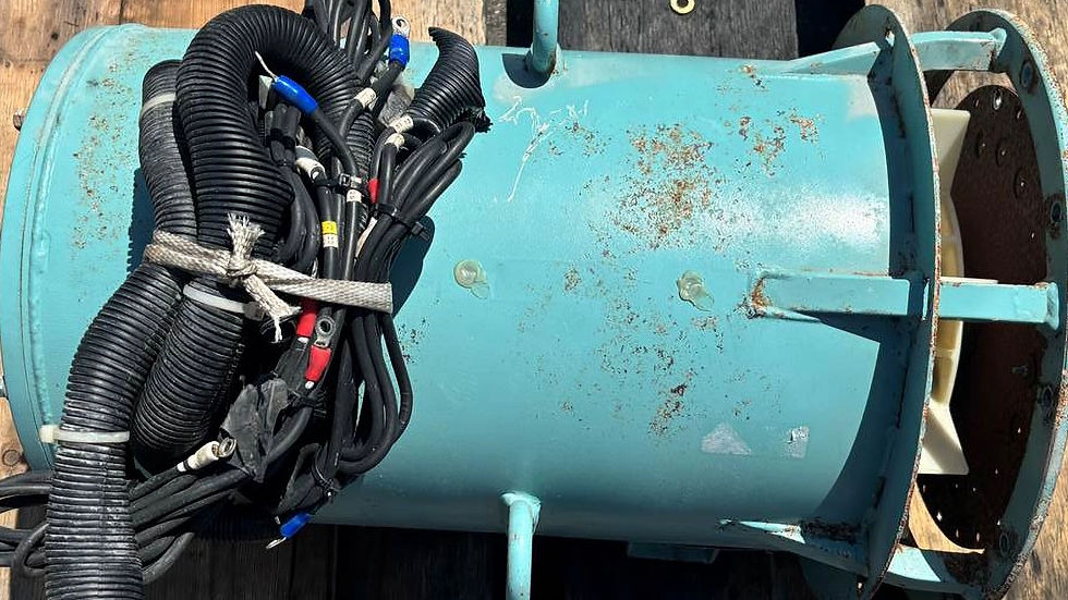
Identify where the 12 leads exit the alternator. They are usually grouped in a terminal box or bundled together. Carefully separate the leads without damaging insulation.
3. Consult the Wiring Diagram
Refer to the alternator’s wiring diagram to understand the expected lead arrangement. The diagram shows how the leads correspond to the stator coils and their internal connections.
4. Measure Resistance Between Leads
Using the multimeter set to resistance mode:
Measure resistance between pairs of leads.
Leads belonging to the same coil phase will show low resistance (typically a few ohms).
Leads from different phases will show no continuity or very high resistance.
Record the resistance values to group leads into three sets of four leads each, corresponding to the three phases.
5. Identify Phase Groups
Each phase has four leads because the stator winding is divided into sections. The 12 leads represent three phases (A, B, C), each with four taps.
Group leads with low resistance between them.
Label these groups as Phase A, Phase B, and Phase C.
6. Determine Lead Functions Within Each Phase
Within each phase group, the leads serve different functions:
Start and end of coils
Taps for different voltage configurations
Neutral point connections
Use the wiring diagram and resistance measurements to identify which lead corresponds to which coil section.
7. Check for Neutral and Common Leads
In wye configurations, a neutral lead connects the three phases at a common point. Identify this lead by checking continuity between the three neutral points of each phase.
8. Verify Lead Identification by Testing Configurations
Once leads are labeled, test the alternator by wiring it in the desired configuration:
For 240V output: Connect leads in a wye configuration with neutral.
For 480V output: Connect leads in a delta configuration without neutral.
Measure the output voltage to confirm correct lead identification.
Practical Tips for Accurate Tracing
Label leads immediately after identification to avoid confusion.
Use color-coded tape or markers to differentiate phases.
Work in a well-lit area to see wire colors and markings clearly.
If available, use a phase rotation meter to verify phase sequence.
Take photos or sketches of your wiring setup for future reference.
Common Challenges and How to Overcome Them
Leads with No Markings
Sometimes leads come without factory markings. Use resistance testing and wiring diagrams to deduce their identity.
Damaged or Worn Insulation
Handle wires carefully. If insulation is damaged, repair or replace before proceeding to avoid shorts.
Complex Alternator Designs
Some alternators have additional taps or special configurations. Always refer to the manufacturer’s documentation for these cases.
Example: Tracing Leads on a Typical 12-Lead Alternator
Imagine you have a 12-lead alternator from a generator designed for both 240V and 480V output.
You start by measuring resistance and find three groups of four leads each.
Group 1 shows low resistance between leads 1, 2, 3, and 4.
Group 2 includes leads 5, 6, 7, and 8.
Group 3 includes leads 9, 10, 11, and 12.
Using the wiring diagram, you identify Group 1 as Phase A, Group 2 as Phase B, and Group 3 as Phase C.
You find the neutral leads by checking continuity between leads 4, 8, and 12.
After labeling, you wire the alternator in wye for 240V and measure the output.
Then, you rewire in delta for 480V and confirm the voltage output matches expectations.
This hands-on approach ensures you understand the lead functions and can confidently work with the alternator.
Safety Considerations When Working with Alternator Leads
Always wear insulated gloves and use insulated tools.
Confirm power is off before touching leads.
Avoid working alone when handling high-voltage equipment.
Follow local electrical codes and standards.
If unsure, consult a qualified electrician or technician.


Comments